Section 29.2
Troubleshooting Flash Code 23, PID 174/FMI 3
This diagnostic condition is typically:
- Open sensor signal circuit
- Open sensor circuit return
- Sensor signal circuit is shorted to the sensor +5 volt supply
Note: This code will only be logged during warm engine operation.
The following procedure will troubleshoot Flash Code 23.
Section 29.2.1
Sensor Check
Perform the following steps to check the FTS/SFT Sensor:
- Turn ignition OFF.
- Disconnect the FTS/SFT Sensor connector.
- Install a jumper wire between sockets 1 and 2 of the FTS/SFT Sensor harness connector. see Figure
"Supply Fuel Temperature Sensor"
.
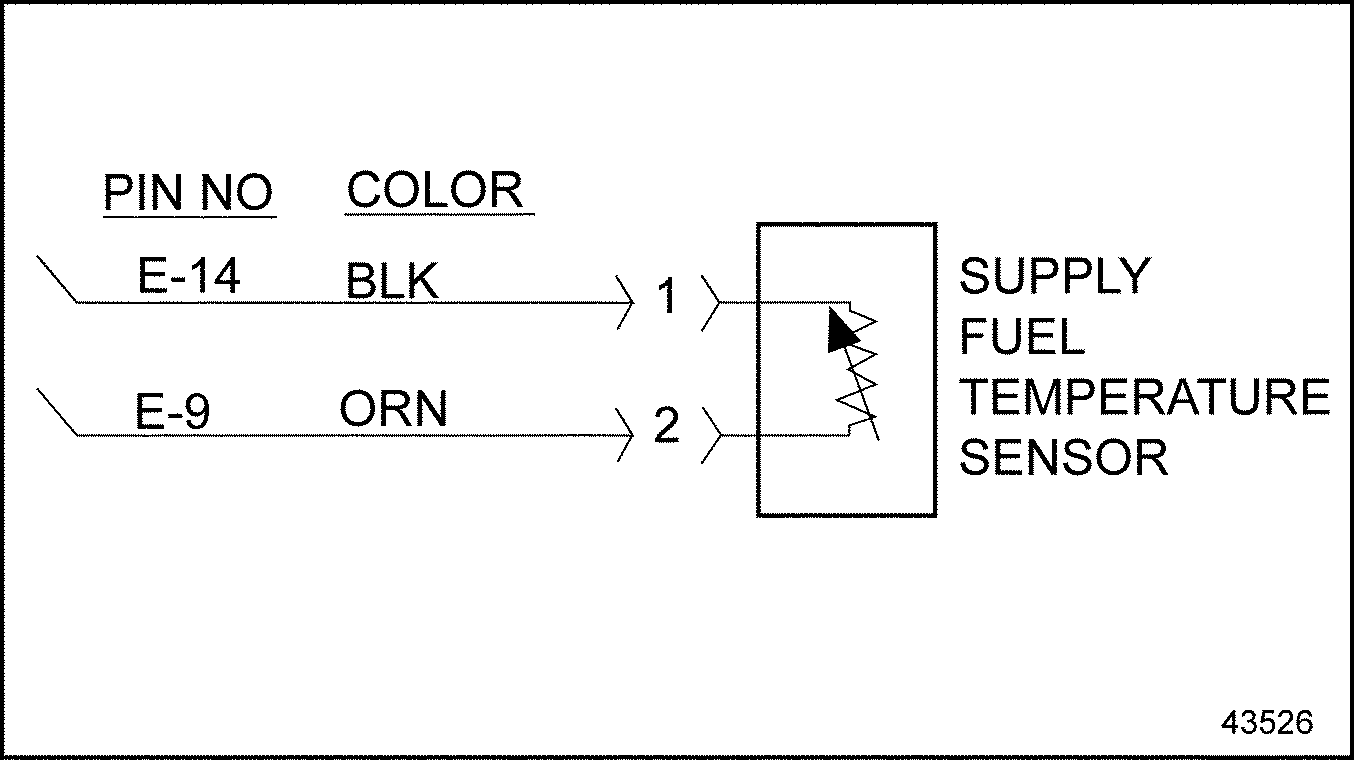
Figure 1. Supply Fuel Temperature Sensor
- Turn ignition ON.
- Read active codes.
- If code p 174/4 and any other codes except code p 174/3 are logged, refer to "29.2.2 Check for Short to +5 Volt Line" .
- If any code except p 174/4 is logged, refer to "29.2.3 Open Line Check" .
Section 29.2.2
Check for Short to +5 Volt Line
Perform the following steps to check for a short to the +5 volt line.
- Turn ignition OFF.
- Remove jumper wire.
- Disconnect the Engine Harness connector at the ECM/ECU.
- Measure resistance between sockets E-9 and E-14 on the Engine Harness connector. See Figure
"ECM/ECU Engine Harness Connector"
.
- If the measured resistance is greater than 100 Ω or open, go to step 5 .
- If the measured resistance is less than or equal to 100 Ω, the signal line E-9 is shorted to the engine +5 volt line. Repair the short; refer to "29.2.3.1 Verify Repairs" .
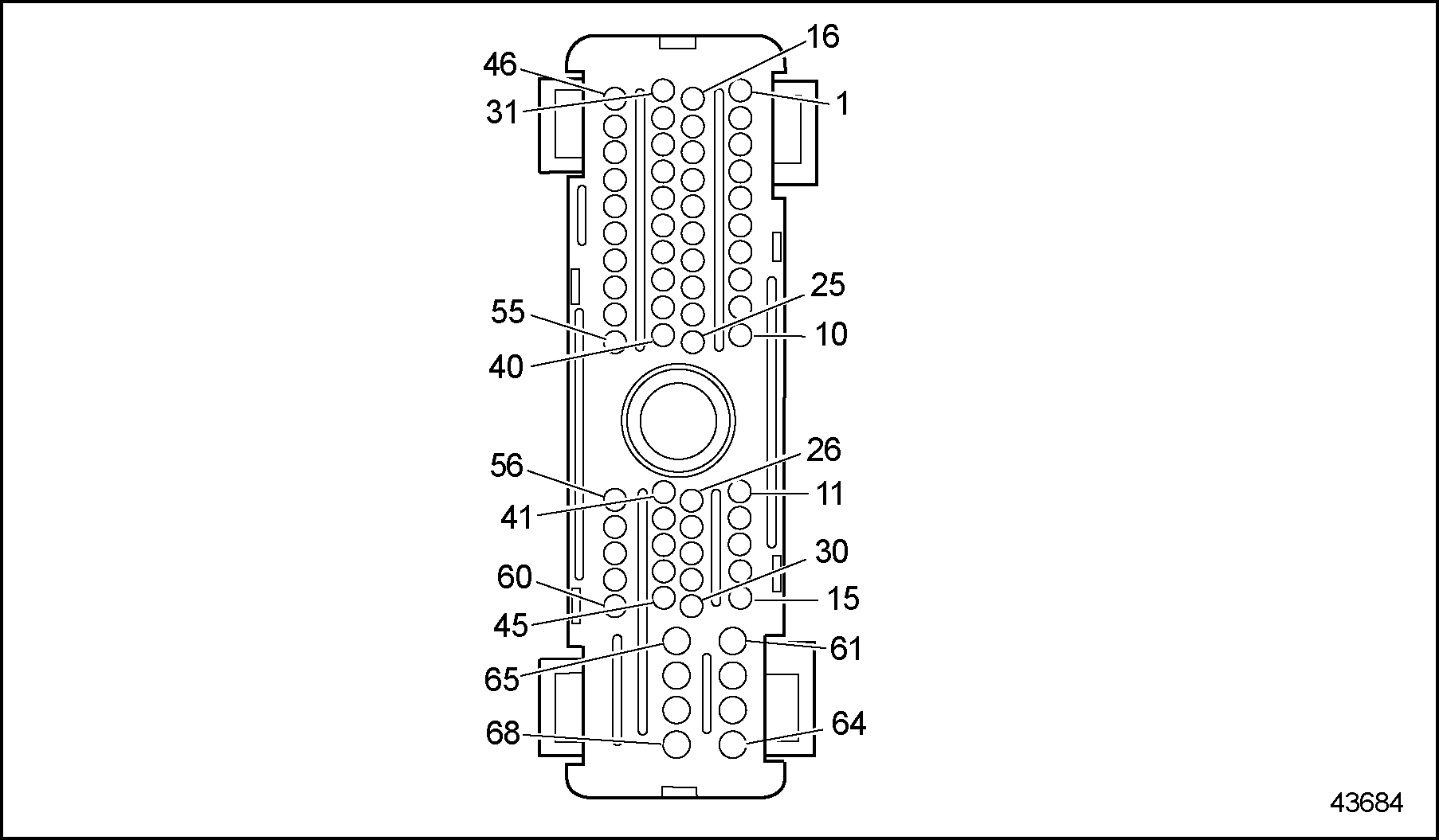
Figure 2. ECM/ECU Engine Harness Connector
- Check terminals at the FTS/SFT Sensor harness connector (both sensor and harness side) for bent, corroded, and unseated pins or sockets. See Figure
"Supply Fuel Temperature Sensor"
.
Figure 3. Supply Fuel Temperature Sensor
- If terminals and connectors are damaged, repair them. Refer to "29.2.3.1 Verify Repairs" .
- If terminals and connectors are not damaged, replace the FTS/SFT Sensor. Refer to "29.2.3.1 Verify Repairs" .
Section 29.2.3
Open Line Check
Perform the following steps to check for an open line.
- Turn ignition OFF.
- Disconnect the Engine Harness connector at the ECM/ECU. The jumper wire is still in place at the FTS/SFT Sensor connector.
- Measure resistance between sockets E-9 and E-14 on the Engine Harness connector. See Figure
"ECM/ECU Engine Harness Connector"
.
- If the measured resistance is greater than 5 Ω or open, the signal line E-9 or return line E-14 is open. Repair the open; refer to "29.2.3.1 Verify Repairs" .
- If the measured resistance is less than or equal to 5 Ω, go to step 4 .
- Check terminals at the ECM/ECU harness connector (both ECM/ECU and harness side) for bent, corroded, and unseated pins or sockets. See Figure
"ECM/ECU Engine Harness Connector"
.
Figure 4. ECM/ECU Engine Harness Connector
- If terminals and connectors are damaged, repair them. Refer to "29.2.3.1 Verify Repairs" .
- If terminals and connectors are not damaged, install a test ECM/ECU. Refer to "29.2.3.1 Verify Repairs" .
Section 29.2.3.1
Verify Repairs
Perform the following steps to verify repairs:
- Turn ignition OFF and reconnect all connectors.
- Turn ignition ON and clear codes with the diagnostic tool.
- Start and run the engine for eight minutes.
- Stop engine.
- Read codes.
- If no codes are logged, troubleshooting is complete.
- If code p 174/3 and any other codes are logged, all system diagnostics are complete. Review this section from the first step to find the error. Refer to "29.2.1 Sensor Check" .
- If code p 174/3 is not logged, but other codes are logged, refer to "18.3 First Step for Diagnosing a Fault Within the DDEC System" .
| Series 60 DDEC V Troubleshooting Guide - 6SE570 |
| Generated on 10-13-2008 |