Before mounting an engine on an overhaul stand, it must be disconnected from the transmission. Details for removing an engine will vary from one application to another. However, the following steps will be necessary, regardless of application:
1. Disconnect the battery cable(s) from the battery(s).
2. Drain the cooling system completely by removing the drain plug in the oil cooler and opening the drain cocks in the cylinder block, thermostat housing and water pump housing. Refer to section 14.6.4.
3. Drain the lubricating oil. Refer to section 14.6.1.
4. Disconnect the inlet fuel line from the primary fuel filter and the outlet line from the upper fitting at the rear of the cylinder head. Refer to section 2.10.1.
5. Remove the air cleaner ducting as necessary for engine removal. Refer to OEM guidelines.
6. Remove the charge air cooler ducting from the turbocharger and intake manifold. Refer to section 6.8.2.
7. Disconnect the exhaust piping from the turbocharger. Refer to section 6.5.2.
8. Disconnect DDEC:
[a] For DDEC I, disconnect the 22-pin DDEC electrical connector. Refer to section 2.18.2.
[b] For DDEC II or III, disconnect the 30-pin DDEC vehicle electrical connector and the six-pin DDEC II power connector or DDEC III/IV five pin power connector. Refer to section 2.16.2, or refer to section 2.17.3.
9. For removal of DDEC V refer to section2.15.2.
10. Disconnect and remove the cranking motor. Refer to section 9.4.2.
11. Remove the alternator and other electrical equipment, as necessary. Refer to section 9.2.2.
12. Remove the air compressor and any air lines, as necessary. Refer to section 11.1.5.
13. Disconnect and remove the coolant hoses.
14. Remove the charge air cooler, radiator, fan guard and other cooling system related parts as necessary to remove the engine. Refer to section 6.8.2.
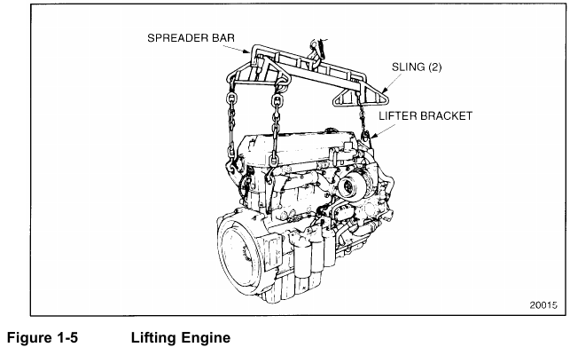
15. Connect a suitable lifting device to the engine using all three lifting brackets (two at the
rear and one at the front).
16. Separate the engine from the transmission .
17. Remove the engine mounting bolts.
18. Lift the engine from its mounts using a suitable lifting device. See Figure 1-5.
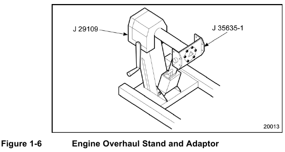
19.Use engine overhaul stand (J–29109) with stand adaptor plate (J–35635–1, part of tool set J–35635–A) for support when stripping a Series 60 engine cylinder block. See Figure 1-6.
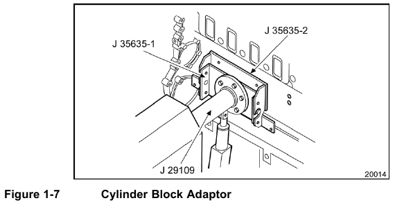
20. Bolt cylinder block adaptor (J–35635–2, part of tool set J–35635–A) to the cylinder block and mate it with the stand adaptor (J–35635–1, part of tool set J–35635–A). See Figure 1-7.
21.The engine is left-side mounted in an upright position. Rotate it in either direction and lock it into position.
22. Remove the fuel filters and adaptor.
[a] For DDEC I engines, remove the inlet and outlet fuel lines connected to the Electronic Distributor Unit (EDU) cold plate, the EDU mounting bolts, and the EDU. Refer to section 2.18.2.
[b] For DDEC II engines, remove the inlet and outlet fuel lines connected to the Electronic Control Module (ECM) cold plate, the ECM mounting bolts, and the ECM. Refer to section 2.17.3.
NOTE:
DDC has discontinued the use of the ECM cold plate on all Series 60 automotive engine models, effective with unit serial number 06R0008950. In place of the ECM cold plate, a No. 6 x 37.92 in. (963 mm) long hose assembly (23504785) is now routed from the fuel pump discharge fitting to the inlet of the secondary fuel filter.
23. Disconnect the harness connector (gray) from the timing reference sensor (TRS) at the lower left corner of the gear case. Remove the TRS from the gear case. Refer to section 2.32.2.
24. Disconnect the harness (black) connector from the synchronous reference sensor (SRS) at the left rear wall of the gear case. Remove the SRS from the gear case. Refer to section 2.30.2.
25. Remove any electrical components, connectors or wiring looms from the engine.
26. With the engine mounted on the overhaul stand, remove all of any remaining
subassemblies and parts from the cylinder block.
[a] To remove the one piece valve rocker cover, refer to section 1.6.2.
[b] To remove the two piece valve rocker cover, refer to section 1.6.3.
[c] To remove the three piece valve rocker cover. Refer to section 1.6.5.
[d] Remove the engine lifter brackets, refer to section 1.5.2.
[e] Remove the crankshaft pulley, refer to section 1.15.2.
[f] Remove the crankshaft vibration damper, refer to section 1.14.2.
[g] Remove the accessory drive, refer to section 1.35.2.
[h] Remove the gear case cover, refer to section 1.10.2.
[i] Remove gear case cover Exhaust Gas Recirculation (EGR) model refer to section 1.11.2.
[j] Remove the camshaft drive gear, refer to section 1.29.2.
[k] Remove camshaft gear assembly compact gear train refer to section 1.26.2.
[l] Remove the bull gear and camshaft idler gear assembly, refer to section 1.33.2.
[m] Remove bull gear and camshaft idler gear compact gear train refer to section1.32.2.
[n] Remove the adjustable idler gear assembly, refer to section 1.30.2.
[o] Remove adjustable idler gear assembly compact gear train refer to section 1.31.2.
[p] Remove the crankshaft timing gear and timing wheel, refer to section 1.34.2.
[q] Remove the gear case, refer to section 1.12.2.
[r] Remove gear case Exhaust Gas Recirculation (EGR) model refer to section 1.13.1.
[s] Remove the camshaft, refer to section 1.28.2.
[t] Remove the cylinder head, refer to section 1.2.2.
[u] Remove the flywheel, refer to section 1.16.2.
[v] Remove the flywheel housing, refer to section 1.18.2.
[w] Remove the oil pan, refer to section 3.11.2.
[x] Remove the piston and connecting rod assembly, refer to section 1.21.2.
[y] Remove the crankshaft, refer to section 1.7.2.
[z] Remove the crankshaft main bearings, refer to section 1.9.2.