Section 8.1
Main Engine Wiring Harness
This section covers removal and installation of the main engine wiring harness for engines equipped with engine mounted ECM unit.
Section 8.1.1
Removal of Wiring Harness
Removing the main wiring harness from the front mounted or rear mounted ECM is identical, except where noted.
- Disconnect batteries.
- Remove screws and connector cover shields from the ECM connector covers; see Figure
"Install ECM Connector Covers"
.
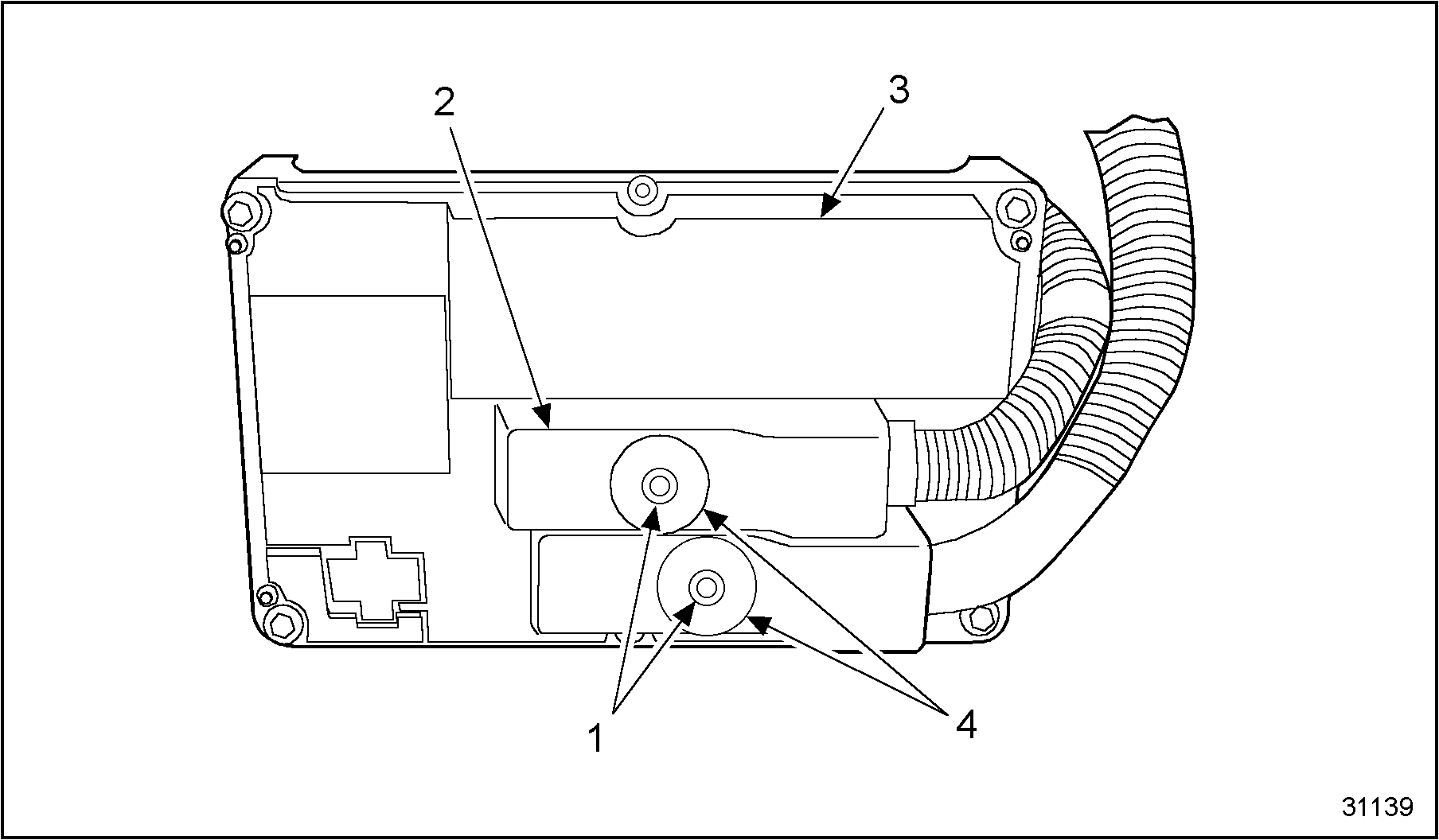
1.Connector Shield Screw
3.Connector Cover
2.Connector Shield
4.Wiring Harness Connector
Figure 1. Install ECM Connector Covers
- Remove ECM connector covers from the wiring harness connectors. See Figure "Install ECM Connector Covers" .
- Loosen the chassis wiring harness connector mounting bolt and remove wiring harness from the ECM.
- Loosen engine wiring harness connector mounting bolt and disconnect engine wiring harness from the ECM. See Figure
"Loosen Wiring Harness Bolt"
and see Figure
"Remove Engine Wiring Harness"
.
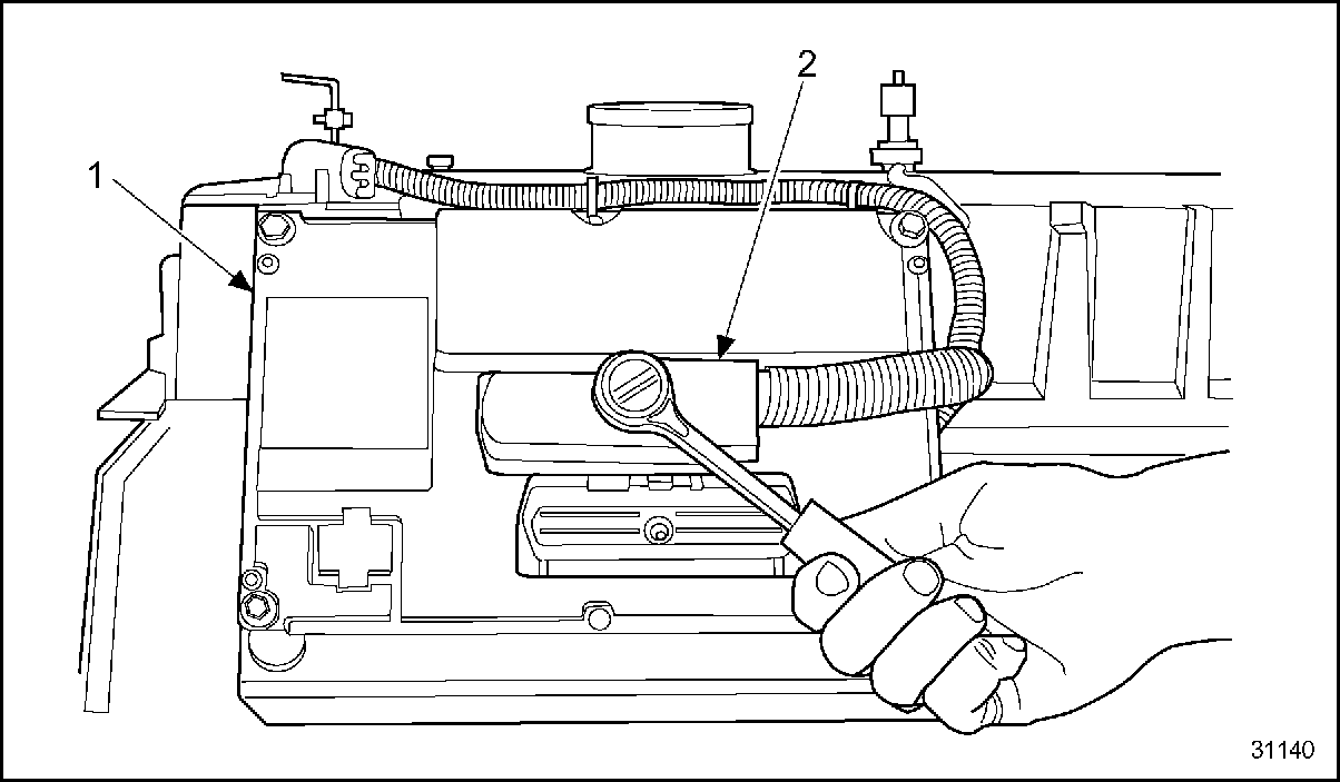
1.ECM
2.Engine Wiring Harness Connector
Figure 2. Loosen Wiring Harness Bolt
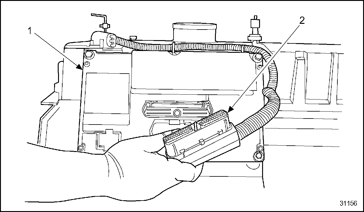
1.ECM
2.Engine Wiring Harness Connector
Figure 3. Remove Engine Wiring Harness
- Pull out the wiring harness connector from the under valve cover fuel injector wiring harness connector. See Figure
"Disconnecting Main Wiring Harness"
.
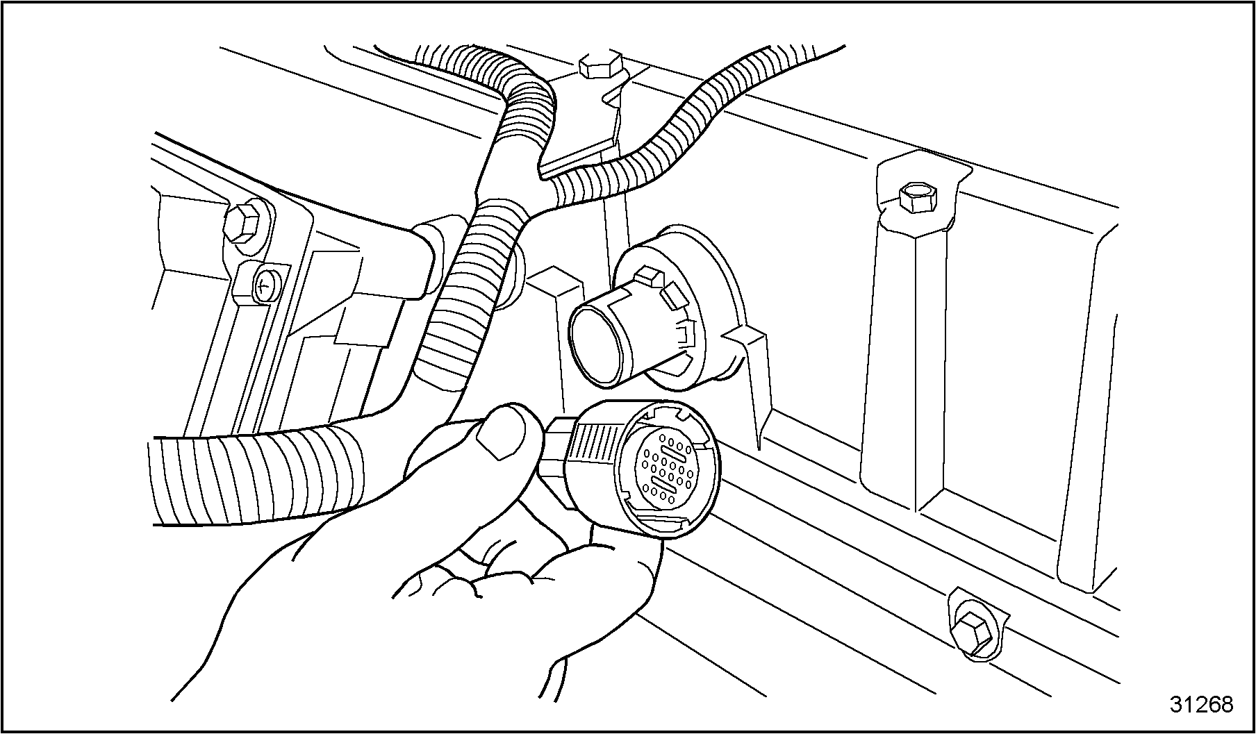
Figure 4. Disconnecting Main Wiring Harness
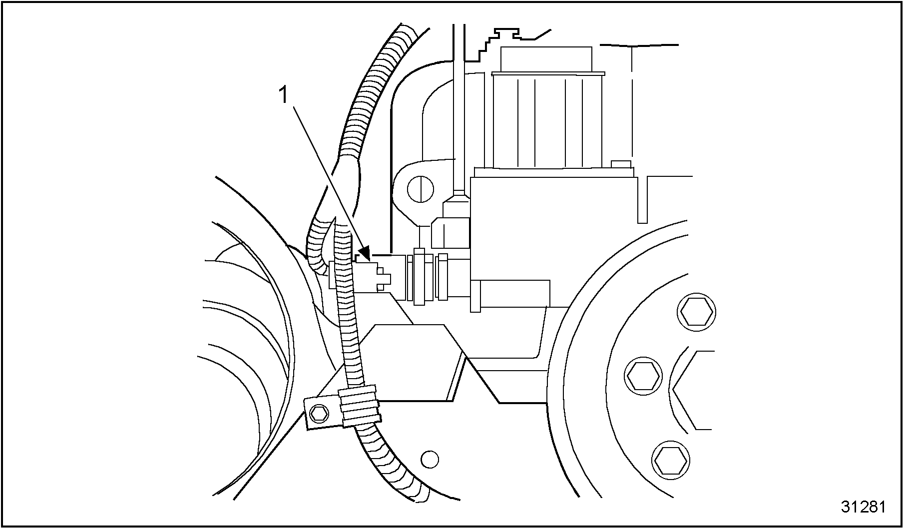
- Unlatch and separate the Injection Control Pressure (ICP) sensor connector from the main wiring harness. If necessary, unscrew the sensor from the supply manifold. See Figure
"Remove Injection Control Pressure Sensor"
.
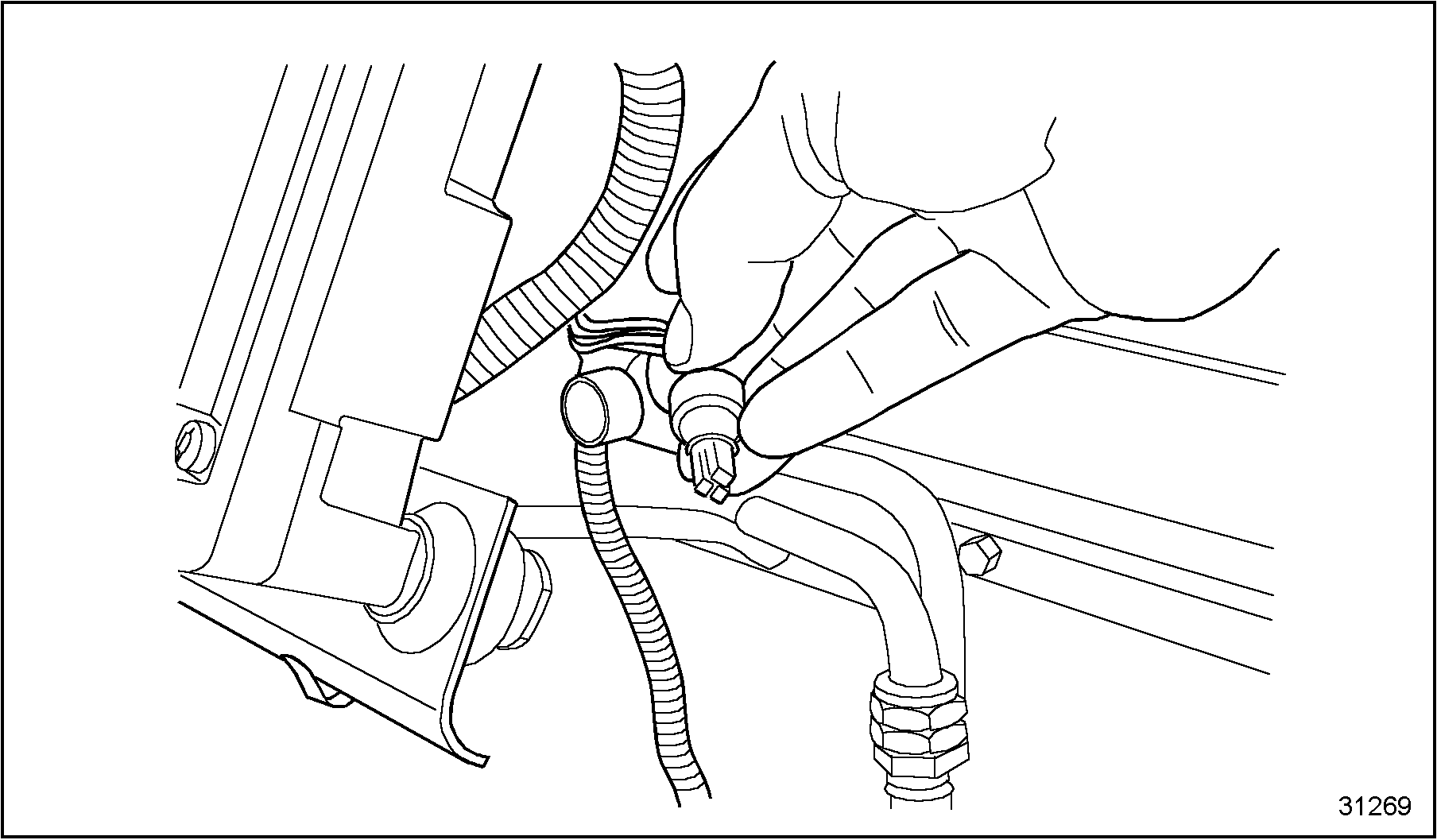
Figure 5. Remove Injection Control Pressure Sensor
- Unlatch and separate the Injection Pressure Regulating valve (IPR) connector from the sensor. See Figure
"Remove Injection Pressure Regulating Valve Connector"
.
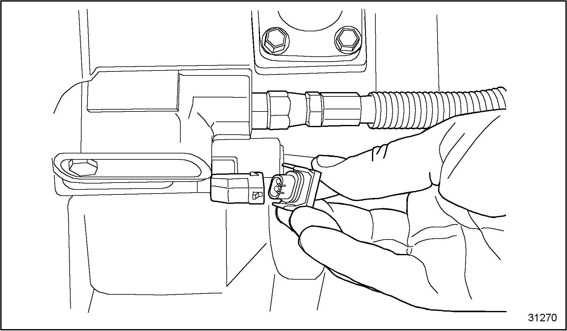
Figure 6. Remove Injection Pressure Regulating Valve Connector
- Unlatch and separate the Engine Oil Pressure (EOP) sensor connector from the main wiring harness. See Figure
"Remove Engine Oil Pressure Sensor Connector"
.
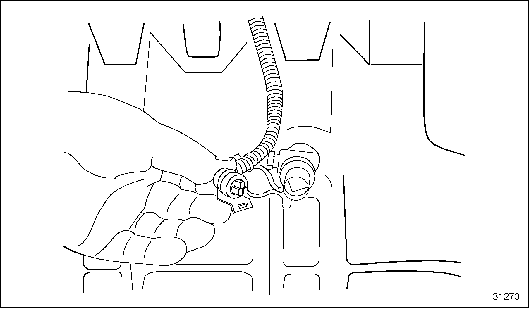
Figure 7. Remove Engine Oil Pressure Sensor Connector
- Unlatch and separate the Manifold Absolute Pressure (MAP) sensor connector, located on top of the valve cover, from the main wiring harness.
- Unlatch and separate Engine Oil Temperature sensor (EOT) connector from the main wiring harness, see Figure
"Remove Engine Oil Temperature Sensor Connector"
. When the EOT sensor is removed from the front cover, oil will leak out the port.
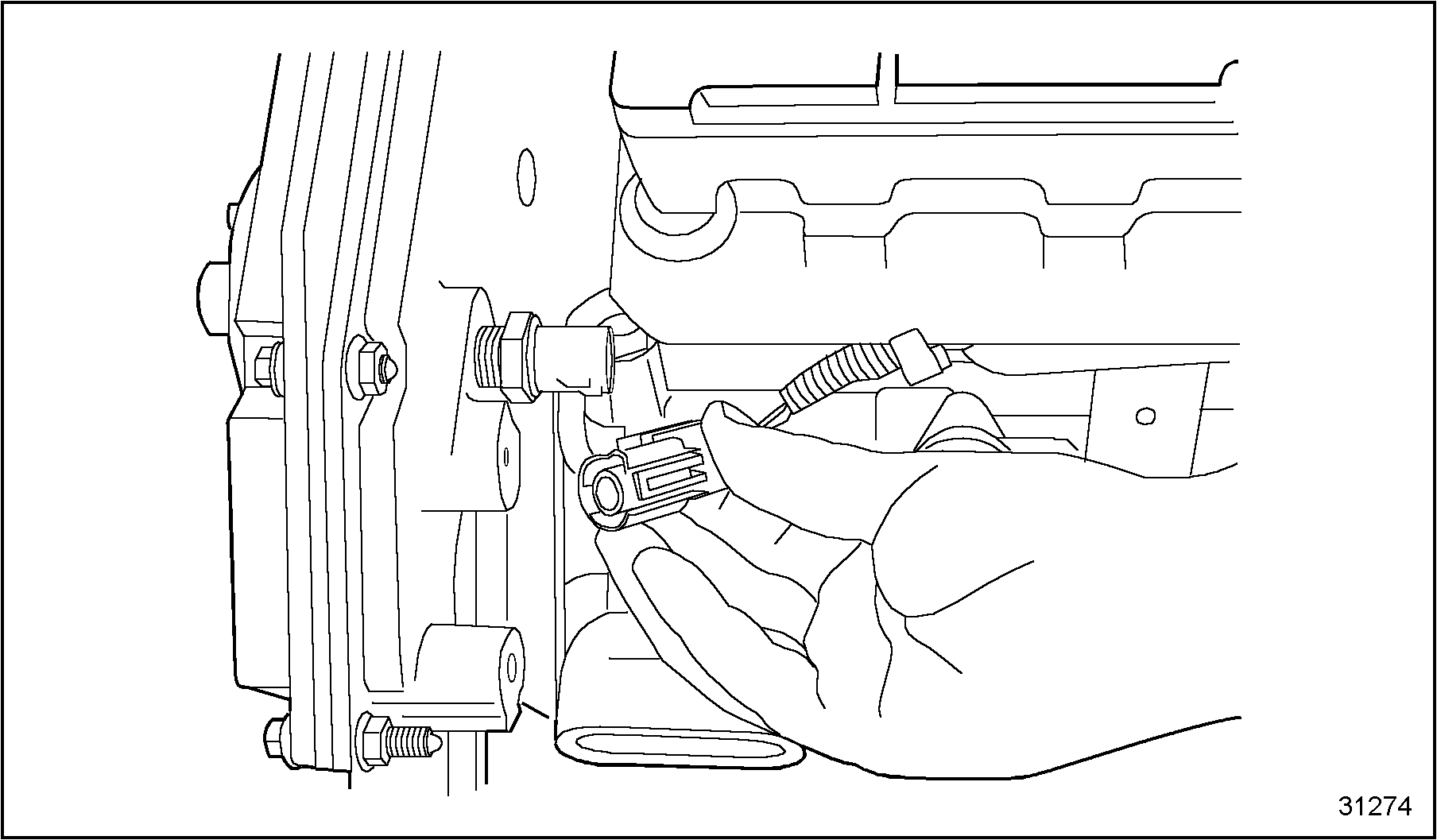
Figure 8. Remove Engine Oil Temperature Sensor Connector
- Unlatch and separate the Engine Coolant Temperature (ECT) sensor connector from the main wiring harness. See Figure
"Remove Engine Coolant Temperature Sensor Connector"
.
1.Engine Coolant Temperature Sensor
Figure 9. Remove Engine Coolant Temperature Sensor Connector
- Unlatch and separate Camshaft Position Sensor (CMP) from the main wiring harness. If necessary, remove CMP mounting bolt and pull CMP sensor from front cover. See Figure
"Removing Camshaft Position Sensor"
.
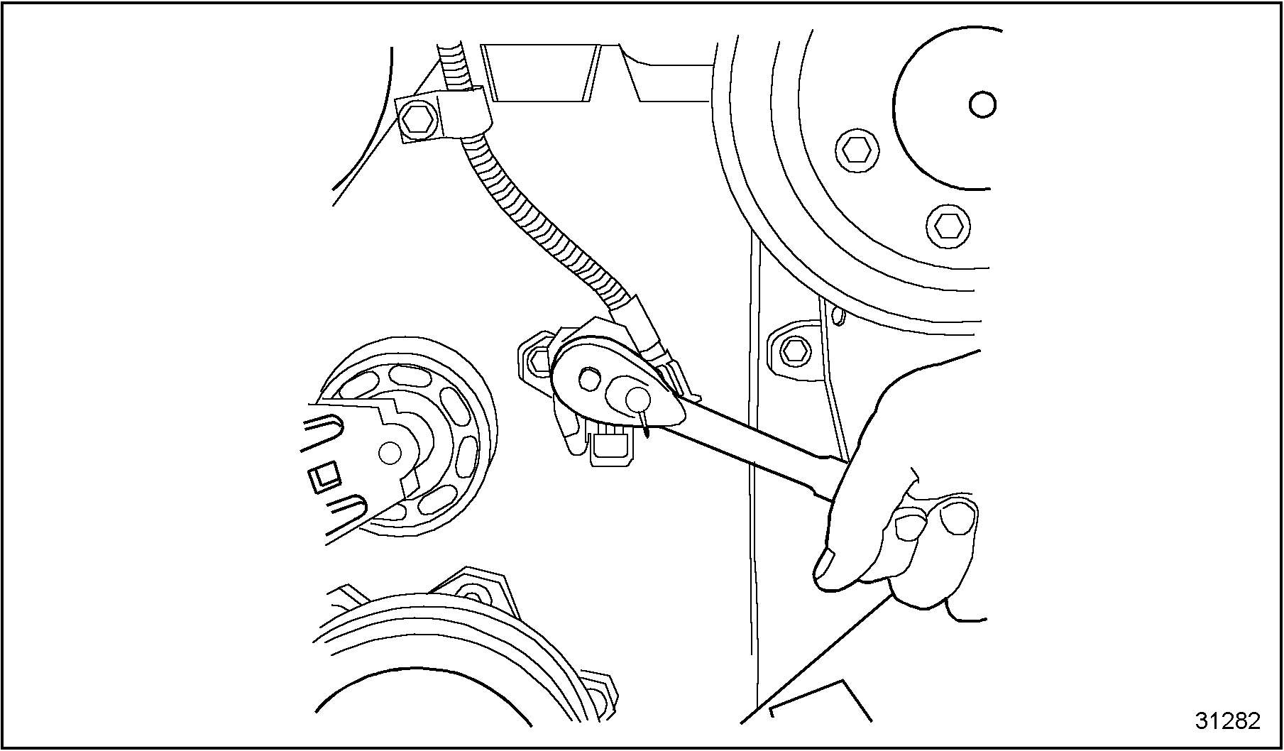
Figure 10. Removing Camshaft Position Sensor
- Remove any wiring harness clamps securing the wiring harness to the engine.
- Carefully lift entire main wiring harness free from the engine.
NOTICE:
To prevent damage to the wiring harness when removing it from the ECM, should any resistance be encountered, do not tug on the wiring harness to free it. Investigate the source of the resistance, and free the connector or clip. Then remove the wiring harness from the engine.
Section 8.1.2
Inspection
Use the following steps when inspecting the wiring harness:
- Be sure to clean any and all Loctite®, if present, from the threads of the sensors.
- Check all connector pins on sensors. If bent or corroded, replace sensor.
- Carefully inspect wiring harness for worn conduit, frayed insulation or heat damage on wires. Refer to the following repair section should repair be necessary.
- Inspect each connector for the following conditions. Replace as required.
- Corroded connectors - green or gray-white deposits on metal terminals.
- Female connector sleeves spread open.
- Terminals incorrectly latched into connector body or "pushed back" relative to other terminals in the same connector.
Note: Use service kit 1 830 337 C91 for replacement of ECM harness connectors that show cracks or damage
- Inspect the engine wiring harness connectors, connector covers and cover shields for cracks, cuts or worn areas. Replace as required. See Figure
"Connector Cover Parts"
.
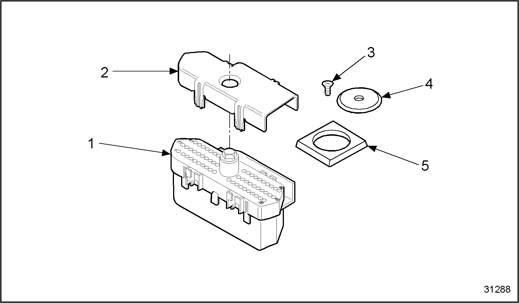
1.Wiring Connector Cover
4.Wiring Harness Connector
2.Connector Cover Shield
5.ECM Gasket
3.Screw
Figure 11. Connector Cover Parts
Section 8.1.3
Assembly of Main Wiring Harness
Use the following steps to assemble the main wiring harness. Assembly procedures for engines equipped with separately mounted ECM and IDM units or engines equipped with the engine mounted ECM are the same except where noted.
- If removed, install the EOP, ECT, MAP and EOT sensors into their proper locations and tighten.
- Install CMP sensor, if removed, into front cover as follows. See Figure
"Camshaft Position Sensor Installation"
.
- If it is necessary to check the clearance of the CMP sensor, refer to "2.6 Verify Camshaft Position Sensor Clearance" .
- Place new O-ring onto CMP sensor and lubricate with clean engine oil. Insert into front cover.
- Secure CMP sensor to front cover with mounting bolt. Tighten bolt.
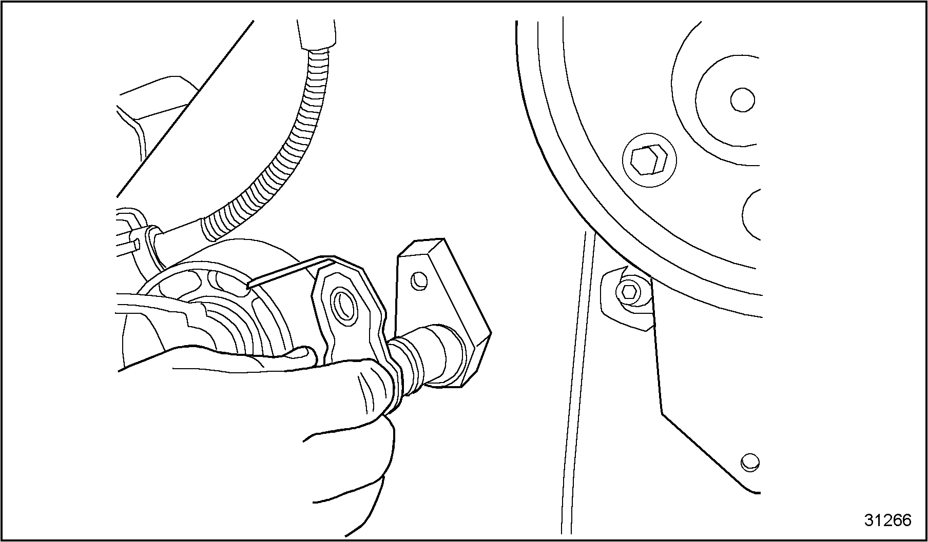
Figure 12. Camshaft Position Sensor Installation
NOTICE:
Ensure that each connector has its ribbed seal in place before installing onto sensor. In some cases, during disassembly the ribbed seal may pull off the connector and remain in the mating socket of a sensor or actuator. A connector assembled without the appropriate ribbed seal can become contaminated with moisture and corrode the terminals resulting in a poor electrical connection.
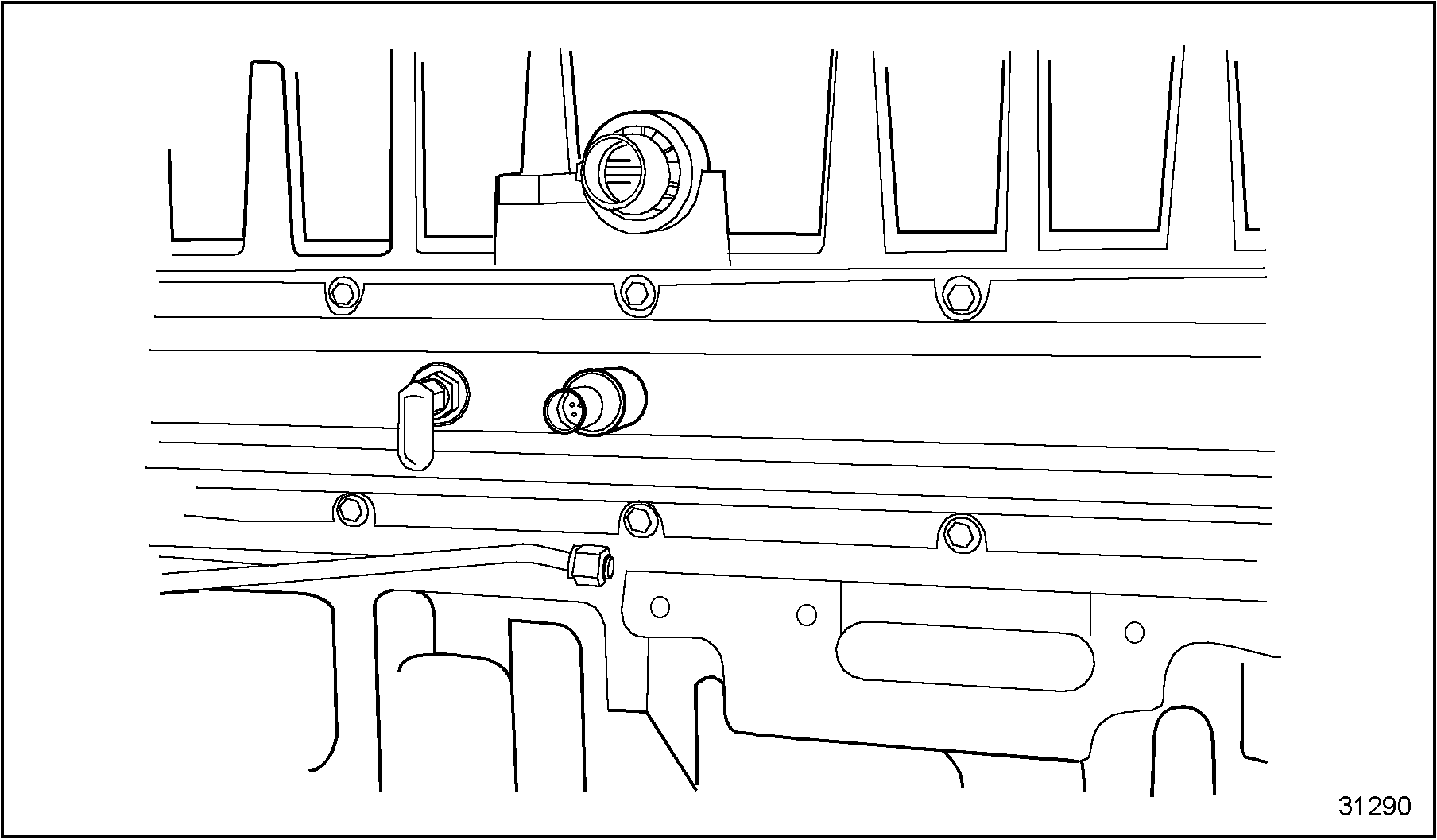
Figure 13. Injection Control Pressure Sensor Into Supply Manifold
- Install wiring harness onto the engine and carefully align connectors with sensors. Push each connector into its mating socket until locking tabs are fully latched.
- Install the two ECM gaskets into the ECM connector receptacles.
- Connect the engine wiring harness to the ECM. See Figure
"Install ECM Connector"
.
1.ECM
2.Engine Wiring Harness Connector
Figure 14. Install ECM Connector
- Tighten the connector retaining screw and torque to specifications. See Figure
"Securing ECM Connector "
. Refer to Specifications "Additional Information"
in Section
.
1.ECM
2.Engine Wiring Harness Connector
Figure 15. Securing ECM Connector
- Install and connect the second wiring harness to the ECM. Torque the connector retaining screw to specifications.
- Install the ECM connector covers, see Figure
"Installing ECM Connector Covers"
, over the wiring harness connectors.
1.Connector Shield Screw
3.Connector Cover
2.Connector Shield
4.Wiring Harness Connector
Figure 16. Installing ECM Connector Covers
- Place the connector shields onto the connector covers and secure with the connector cover shield screw. See Figure "Installing ECM Connector Covers" .
- Install wiring harness routing clips.
- Connect the batteries.
| Series 40E Service Manual - 6SE410 |
| Generated on 10-13-2008 |